The challenge
KeolisAmey had been commissioned by Transport for Wales (TfW) to develop the Preliminary Design for a public transport transformation in the Cardiff and Valleys region. Amey was appointed by Transport for Wales (TfW) to carry out the stage C design for the proposed new Core Valley Lines (CVL) Metrolink Maintenance Depot at Taffs Well.
This included:
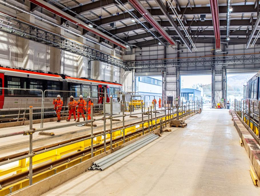
- The design of a new maintenance shed sufficiently large to accommodate 3 maintenance roads each capable of taking 2no 3 carriage Metro vehicles complete with inspection pits, high level gantries, overhead cranage, warehousing, electrical and mechanical workshops, a wheel lathe, a bogie wash facility, battery storage, an external mechanical train wash and an underframe cleaning zone.
- A new office building to accommodate both maintenance and operations staff including office accommodation, welfare facilities, meeting rooms, training facilities, plant rooms and server rooms.
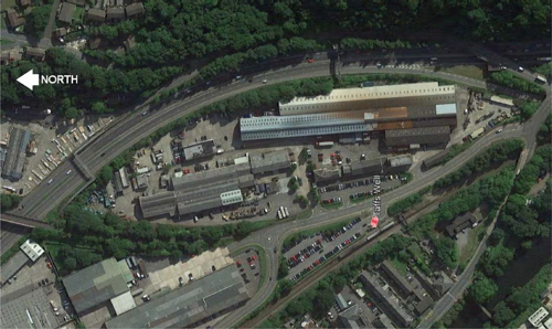
Site
The site was formerly the Garth Works Industrial Estate and is strategically located approximately 5.8 miles (9.3 kilometres) Northwest of Cardiff Central Station, will be the location for all the new CVL’s Metro Vehicle (MV) delivery, maintenance and operation. The Maintenance Shed building would be critical for achieving this requirement. Initially, the Maintenance Shed will be used for commissioning and local testing of the first MVs. Once passenger service commences the depot will then support all aspects of maintenance from consumable replenishment to overhaul and wheel reprofiling.
Our approach
Design Brief
The Maintenance Shed will fulfil the requirements of two key user groups.
- The new Metro vehicle Maintenance Team
- TfW Operations staff
The Amey scope included:
- Developing the design brief in consultation with TfW management, Operations staff and Stadler.
- Carry our feasibility study including options
- Participating in and providing illustrative material for consultation with the local planning authority.
- Providing drawings for a Section 73
- Support Planning Consultants during the S73 submission in overcoming
- Developing survey scopes to enable TfW to procure these surveys prior to the commencement of detailed
The architectural team lead the client and stakeholder interface as well as lead the multidisciplinary team management which include the following disciplines:
- M & E Engineers
- Structural Engineer
- Highways Engineers
- Drainage Engineers
- Geotechnical
- Ecology and Environmental
- Planning Consultants
- Fire and Security Consultants
- Telecoms Engineers
- Track Engineers
- OLE Engineers
- Stadler (Train Manufacturer)
- Signals Engineers
A key aim for TfW was to ensure that during Design Stage C as much enabling investigations were carried out enabling the detailed Design Stage E to be implemented quickly.
Planning Considerations
Through the Amey Consulting Framework, specialist Planning Consultants (Axis) were appointed to advise on the Planning Policy and prepare the Section 73 application.
The Property Design Architects and Project Managers coordinated with the Planning Consultants in developing the Depot design and the preparation of the Section 73 submission which was carried out in parallel to ensure any planning requirements indicated by the local authority were incorporated into the design prior to the submission.
This dialogue help identify that the local authority was concerned about the impact of the site development on an adjacent residential property and in particular the possibility of noise and light pollution. The design was subsequently developed in such a way as to mitigate these concerns. As well as the concerns of local residents, there were also concerns raised over what effect the development would have on the Taff cycle trail that skirts the west boundary of the site. Meetings were held with representative from local cycling groups and Sustrans to identify their concerns and come up with solutions.
The Maintenance Shed and Office Building
The Architects attended a number meetings with stakeholders including representatives for Train Drivers, Conductors, Revenue Protection Staff, Union representatives, HR staff, Maintenance Engineers as well as experts in the operation of electrified trams and trains.
As a direct result of this, further detailed requirements were developed with KeolisAmey’s operations personnel, stakeholders and coordinating engineering disciplines to inform the Stage C design for the operational and associated staff and welfare requirements for the Taff’s Well Depot.
The Depot building was able to accommodate all the operational staff identified to be critical to the operations of the Depot including all strategic functions for operation of the maintenance, cleaning, revenue protection, fleet and crew management.
The information gained from these meetings greatly informed the layout of the design in ensuring that there were efficient workflow patterns and circulation routes and. Due to the complex nature of the Stadler requirements, accommodation 'adjacencies' diagrams were prepared to understand and discuss the relationship between different spaces and activities
As part of this exercise efficiencies were found in the accommodation requirement where common facilities could be shared to ensure savings in capital costs as well as maintenance costs.
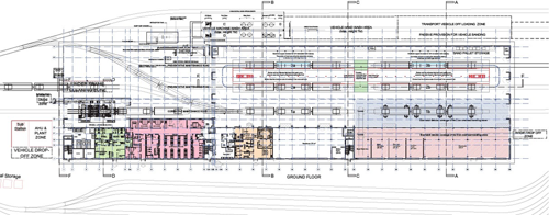
Figure 2: Ground Floor Plan of the Maintenance Shed and Office Building
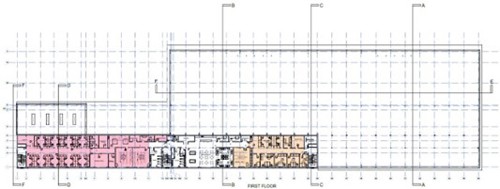
Figure 3: First Floor Plan of the Office Building
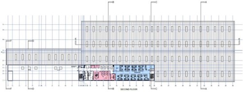
Figure 4: 2nd Floor Plan of the Office Building
Gatehouse Building
When considering the need to protect the site against a potential act of terrorism aimed at disrupting the rail network it was recognised that the most likely threat to the depot site would be theft of materials, loose equipment, property from staff cars and vandalism (such as graffiti damage) to the trains in the stabling area.
Crucial to this would be the location and design of the gatehouse which would control access to and from the site as well as taking delivery of mail and parcels into the site.
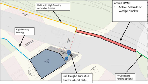
Figure 5: Gate House Location
Master Plan
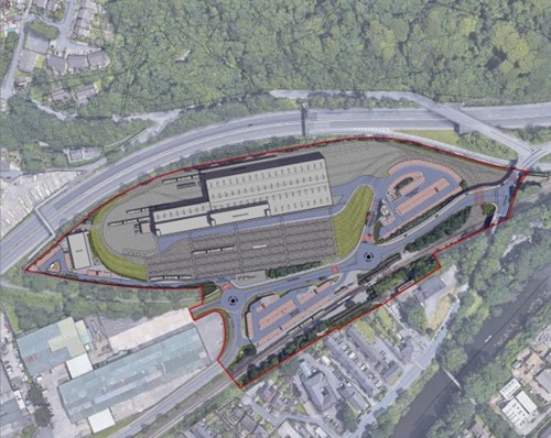
Figure 6: Taffs Well Maintenance Depot Masterplan including the CVLICC building and new Taffs Well Station car park
In developing the masterplan the Architectural team worked closely with the KeolisAmey and other design disciplines including:
- Highways Engineers : Determining the optimum layout for the staff car park and vehicle manoeuvring areas within the site
- OLE Engineers: in planning the layout of the OLE masts and Gantries within the stabling areas to establish how the masts could be located a to allow cleaning staff and drivers access to the Metro vehicles safely when in the stabling area
- Track Engineers: in determining the track layout within the stabling area to accommodate up to 30 Metro 3 carriage units whilst maintaining safe walkway routes to and from the Depot building.
As the Depot would be use throughout the night the final Stage C site layout had the Depot Building located as far as possible from the residential area with the Mechanical wash area on its east side to avoid problems of noise.
CAD and 3D Software Used
The early layouts for the Maintenance and Depot Building were developed in AutoCAD as this allowed quick sketches to be made for dissemination and discussion. These were also used to rapidly develop a simple 3D model using SketchUp. These models allowed the planning consultants to engage meaningfully with the local planning authority to not only convey not just the massing of the buildings but also the proposed palette of external materials at a time when internal for the building was still being developed.
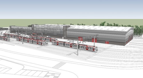
Figure 7: SketchUp model showing the Depot Buildings looking east across the stabling area
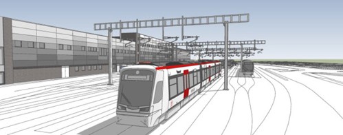
Figure 8: View from within the stabling area looking south
As the internal layouts of the building began to firm up and there was encouraging feedback from the local authority the structural design was progressed using ‘Robot’ software. The architectural design of the building was then taken forward in Revit for the purpose of BIM coordination and clash detection culminating in an i-model in Microstation.
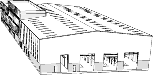
Figure 9:Maintenance Depot Building Revit 3D model
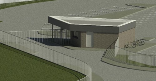
Figure 10: View of the Revit 3D model of the Security Gatehouse.
Benefits
There were several benefits to come out of this Stage C Design and Section 73 Submission:
- The Section 73 Application was
- The effort spent at Design Stage C considerably de-risked the programme and delays for the next design
- The key stakeholders were engaged in the process throughout to allow them to contribute to the design and to help them in understanding what they needed for their current and future operational
- From the outset of the project all key disciplines contributed to the development of the design to ensure a co-ordinated
- The use of 3D modelling of the project not only enabled key decisions on massing and layout to be discussed and agreed at an early stage of the process but also provided a useful in PR tool when it came to keeping the public abreast of the